How to calibrate the SI5351 oscillator crystal without expensive instruments
In radiofrequency, precisely adjusting an oscillator without tools like oscilloscopes or frequency counters can be a challenge. However, together with EB1A, we discovered that it’s possible to achieve an accurate calibration of the SI5351 module using a simple JavaScript calculation tool, ideal for DIY projects like WSPR.
Project goal
We want the oscillator to be as close as possible to the desired frequency (in this case, 14 MHz). We’ll use a calibrated receiver, such as a radio or an SDR, to measure the resulting frequency and, with this data, correct the frequency of the SI5351’s crystal.
⚠️ Warning: this way of calibrating the SI5351 works correctly for transmitting on a given band (the one you calibrate with). If you calibrate at 10MHz but then transmit at 144MHz you will not have the frequency centered.
Required tools
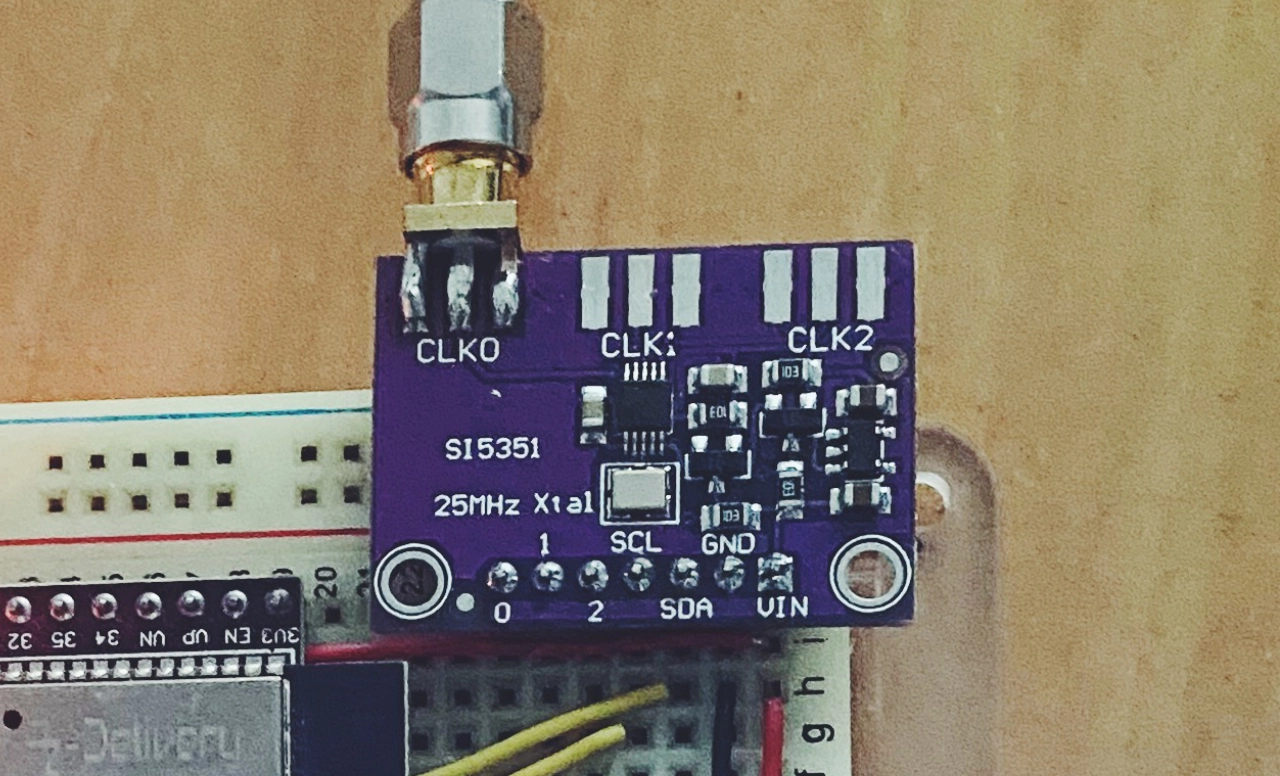
- SI5351 Module and an Arduino or ESP32 microcontroller.
- The Si5351Arduino library (available on GitHub: etherkit/Si5351Arduino).
- A calibrated radio or SDR (to compare the resulting frequency).
Preparation: Arduino code for initial setup
To start, install the library and set the initial crystal frequency to 25 MHz. Next, set the desired frequency to 14 MHz. Upload the code and measure the resulting frequency on your radio or SDR.
Value 4 value⚡️
If the content has been useful to you, please consider supporting me so that I can create more articles like this. Lightning address (only for Lightning payments): [email protected]
I have prepared a test code for calibration that, once connected, emits a signal at 14 MHz.
#include <si5351.h>
#include "Wire.h"

#define SI5351_REF     25000000UL         // si5351’s crystal frequency, 25 Mhz or 27 MHz
unsigned long freq     = 14000000UL;      // Change this for different band frequencies, unit is Hz.

Si5351 si5351;

void setup()
{
  Serial.begin(115200);
  while (!Serial)
    ;

  Serial.println("Initializing radio module");

  bool i2c_found;

  // Start serial and initialize the Si5351
  i2c_found = si5351.init(SI5351_CRYSTAL_LOAD_8PF, SI5351_REF, 0);
  if(!i2c_found)
  {
    Serial.println("Device not found on I2C bus!");
  }

  // Set freq and CLK0 output
  si5351.set_freq(freq * 100, SI5351_CLK0);
  si5351.drive_strength(SI5351_CLK0, SI5351_DRIVE_8MA); // Set for max power, 10dbm output

  // Test the output for 60 seconds
  si5351.set_clock_pwr(SI5351_CLK0, 1);
  Serial.println("Testing singal");
  delay(500);

}

void loop()
{

}
Calculating the adjusted crystal frequency
To adjust the crystal, we’ll use a small JavaScript tool that calculates the precise frequency that should be set for the crystal to achieve the desired frequency.
- Enter the desired frequency: in this case, 14 MHz (enter it in Hz: 14000000).
- Enter the obtained frequency: the frequency observed on the radio or SDR, for example, 14.055000 MHz(14055000 Hz).
- Enter the initial crystal frequency: the nominal frequency of the SI5351’s crystal, typically 25 MHz (25000000 Hz).
By clicking Calculate, the tool will output the adjusted crystal frequency, which you should use in your Arduino sketch instead of the initial frequency.
With this method, you can accurately adjust the SI5351 without specialized instruments. This solution is practical for radio enthusiasts and hobbyists, providing an excellent way to optimize your project without additional costs.
Adjusted crystal frequency calculation
Enter the values to calculate the adjusted crystal frequency:
