MASN: A Simple and Open-Source Solar Node for Meshtastic
Anyone approaching Meshtastic usually finds the same thing: tutorials full of tangled wires, tiny solder joints, and boards designed for people with solid electronics experience. That’s discouraging for anyone just getting started — and even more frustrating if your goal is to build a stable solar-powered node for the roof or the field.
In A Coruña, a group of enthusiasts and makers began meeting at Bricolabs to build nodes using affordable designs like fakeTek and EA3GRN’s videos. The experience was fun, but it also revealed a clear issue: the classic solar setup was overly complex and far from beginner-friendly.
From that need came MASN (Mesh Autonomous Solar Node) — a PCB designed so anyone can assemble a fully autonomous solar node in about an hour, without microscopes or messy wiring. The idea isn’t just to make it work, but to help you learn through the process. Building your own node gives you a deeper understanding of the Meshtastic ecosystem and lets you get the most out of it.
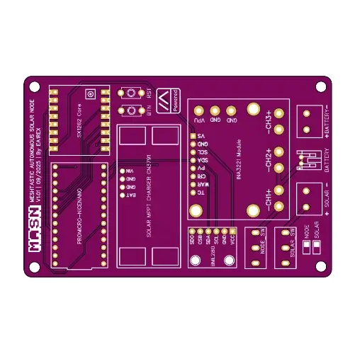
MASN PCB variants
MASN currently has two variants, identical in every aspect except for the LoRa radio module they use. The schematic, firmware, assembly process and overall behavior are exactly the same.

Value 4 value⚡️
If the content has been useful to you, please consider supporting me so that I can create more articles like this. Lightning address (only for Lightning payments): [email protected]
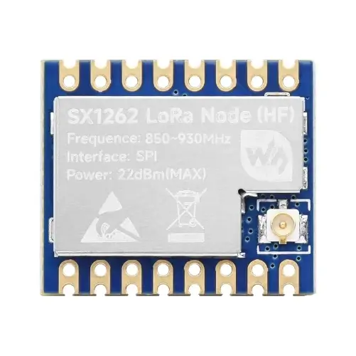
MASN – Core1262 version
Uses the Waveshare Core1262 HF module, based on the SX1262 chip. This is the original version of the project.
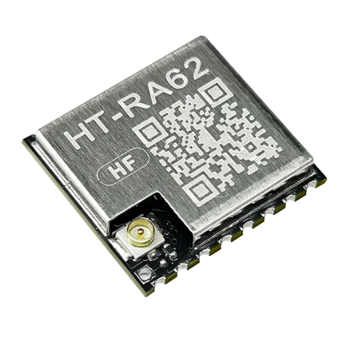
MASN – HT-RA62 version
Uses the HT-RA62 module. It is functionally compatible and intended as an alternative to the Core1262.
Throughout the article, most references mention the Core1262 version. If you build the HT-RA62 variant, the process is exactly the same. You only need to select the corresponding PCB and radio module in the bill of materials.
What MASN Solves
MASN is designed to simplify a process that, in its classic version, is messy and impractical.
Breadboard-based builds often end up with a jungle of wires, unreliable connections, and an overall setup that easily leads to mistakes.
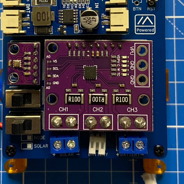
The MASN PCB solves this by integrating everything into a single, compact design.
It’s easier to see the difference when you compare them:
Advantages
- Uses only THT components, easy to solder.
- Integrates all connections into the board — no messy wiring.
- Accepts standard modules that plug in directly.
- Includes an MPPT solar charger and telemetry features.
- Simplifies maintenance: swap a module without rebuilding the whole node.
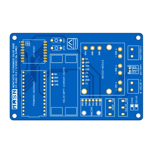
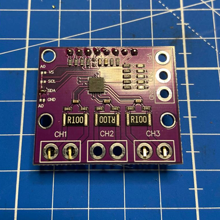
MASN PCB Specifications
Main Components
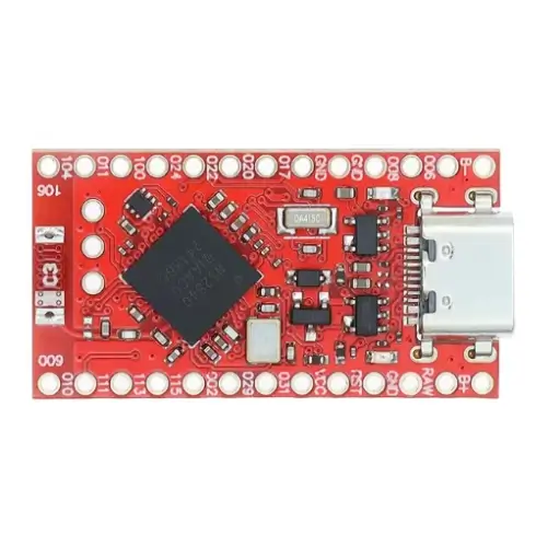
- MCU: NiceNano (NRF52840)
- LoRa module: Waveshare Core1262 HF (MASN PCB Core1262 version) or HT-RA62 (MASN PCB HT-RA62 version), both for EU868 or any other band allowed in your region.
- Solar Charger: MPPT CN3791
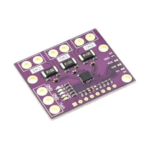
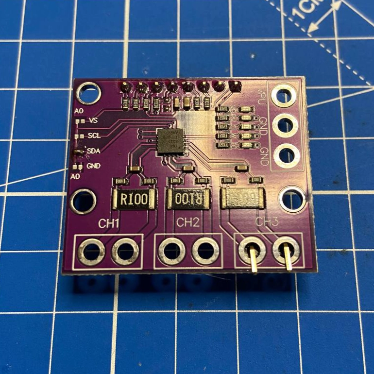
- Current and Voltage Sensor: INA3221 (three channels)
- Channel 1: node & sensors.
- Channel 2: output of the MPPT module.
- Channel 3: solar panel.
- Temperature and Humidity Sensor: BME280
- User and Control Buttons
- Connectors for Solar Panel, Battery, and Antenna
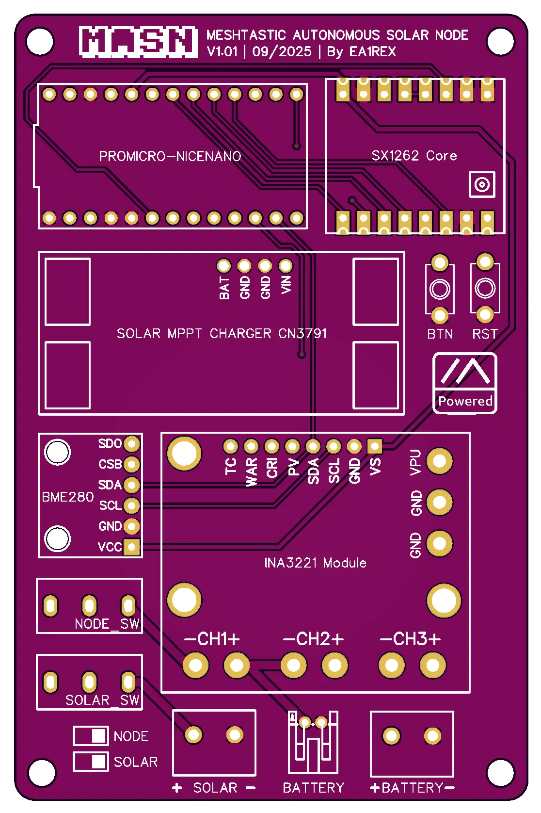
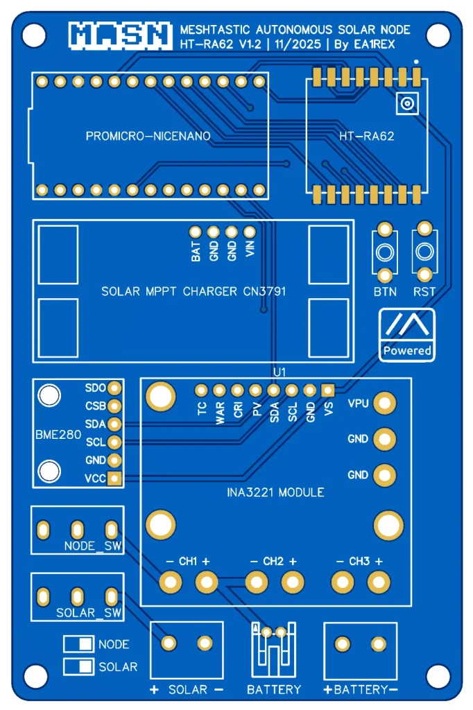
Dimensions and Mounting
- PCB Size: 63.4 mm × 96.9 mm
- Mounting Holes: 56.7 mm × 90 mm
MASN Core1262 schematic
MASN HT-RA62 schematic
Bill of Materials (BOM)
The node’s electronics are built from the following components.
Since purchase links may stop working over time, we’ve also included reference photos for each part so you can easily identify and source them elsewhere if needed.
In a second block, you’ll find the optional enclosure materials — you can mount the PCB in any weatherproof box you already have or can find.
MASN Core1262 Components
| Part | Qty. | Cost | Source | Notes |
|---|---|---|---|---|
| MASN Core1262 PCB | 1 | 5€ | Download | |
| Waveshare Core1262 HF LoRa Module | 1 | 8,30€ | Aliexpress | Choose 868 MHz version (for EU) |
MASN HT-RA62 Components
| Part | Qty. | Cost | Source | Notes |
|---|---|---|---|---|
| MASN HT-RA62 PCB | 1 | 5€ | Download | |
| HT-RA62 LoRa Module | 1 | 6,74€ | Aliexpress |
Components shared by both versions
| Part | Qty. | Cost | Source | Notes |
|---|---|---|---|---|
| NiceNano (NRF52840) | 1 | 3€ | Aliexpress | Get the red PCB version |
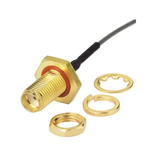
| Antenna Cable UFL to SMA | 1 | 2€ | Aliexpress | 15 cm female version |
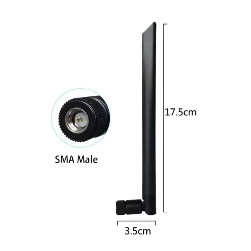
| GrandWisdom 868 MHz Antenna | 1 | 3,40€ | Aliexpress | SMA male connector |
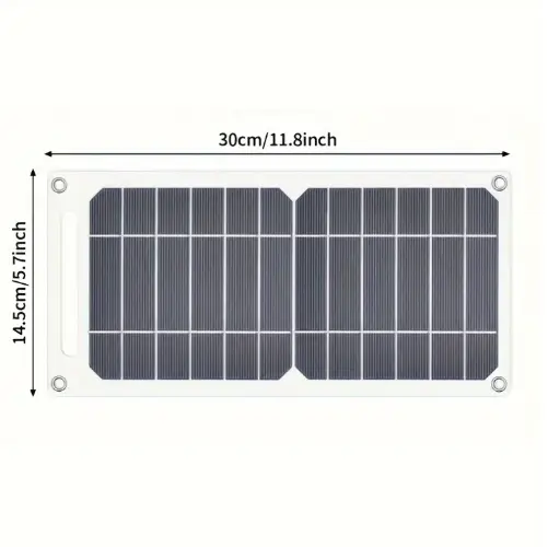
| 5V Solar Panel | 1 | 6,89€ | Aliexpress | Claims 35 W, but not real |
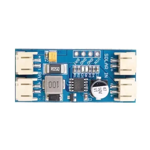
| MPPT CN3791 Charger | 1 | 2,20€ | Aliexpress | Select the 6V version |
| INA3221 Current Sensor | 1 | 1,72€ | Aliexpress | Buy the purple one, not the black |
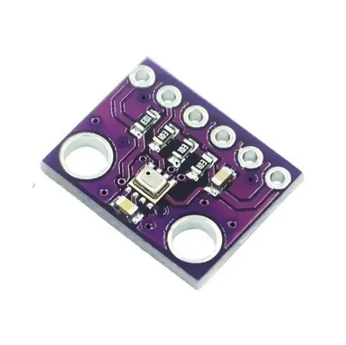
| BMP280 Temperature/Humidity Sensor | 1 | 0,94€ | Aliexpress | Choose 6-pin, 3.3 V version |
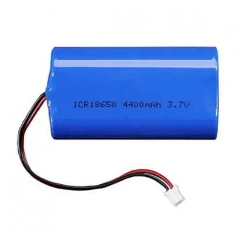
| Li-ion Battery 4400 mAh / 3.7 V | 1 | 10€ | Aliexpress | With PH2.0 connector and BMS (Battery Management System) |
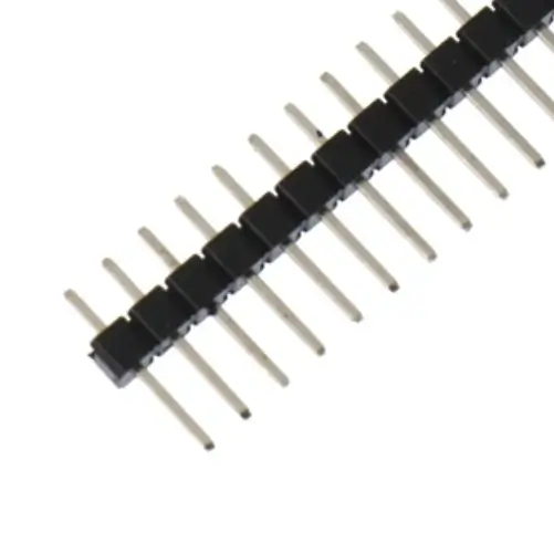
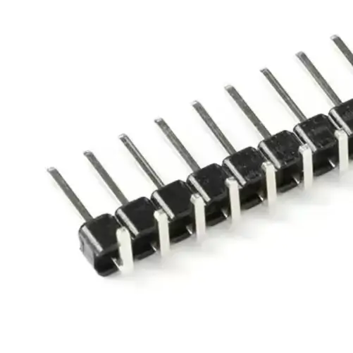
| 40-pin Straight Headers 2.54 mm | 2 | 1,4€ | Aliexpress | |
| 40-pin 90° Headers 2.54 mm | 1 | Aliexpress | ||
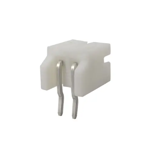
| 2P JST PH 2.0 mm Battery Connector | 1 | 1,62€ | Aliexpress | |
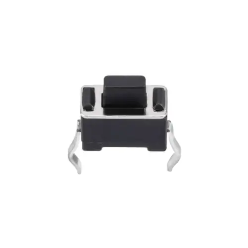
| Push Buttons 3×6×5 mm | 2 | Aliexpress | ||
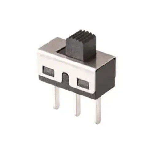
| SS12D10 Switches | 2 | 0,99€ | Aliexpress | |
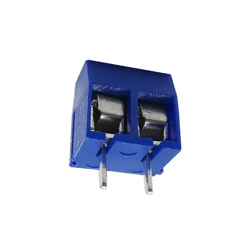
| 2P Screw Terminals for Battery/Solar | 2 | 1,80€ | Aliexpress |
Enclosure Materials (Optional)
| Part | Qty. | Cost | Source | Notes |
|---|---|---|---|---|
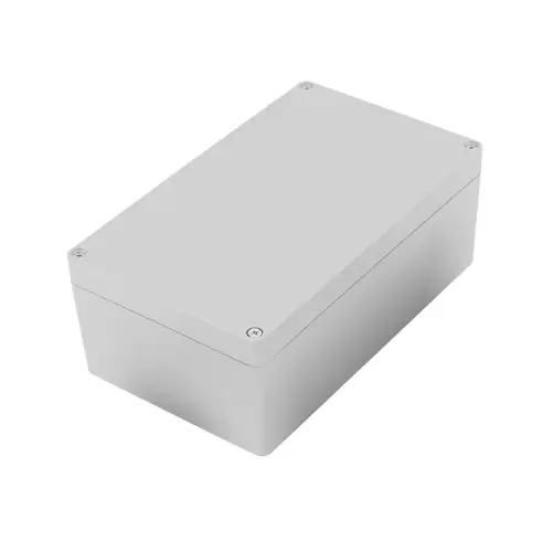
| Weatherproof Electrical Box 158×90×60mm IP65 | 1 | 5,69€ | Aliexpress | |
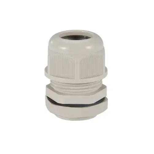
| Vent Plug M5×0.8-7 IP67 | 1 | 2,76€ | Aliexpress | |
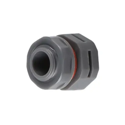
| Cable Gland M12 IP68 | 1 | 1,67 | Aliexpress | Fits 3 – 6.5 mm cables |
| Solar Panel Cable | 1 | – | – | Any you have on hand |
| 3D-Printed Mount for Battery & PCB | 1 | Download | Ask a friend with a 3D printer | |
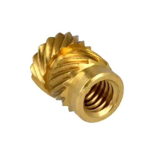
| Threaded Inserts M2.5×5 mm OD 3.5 mm | 4 | 2,34€ | Aliexpress | |
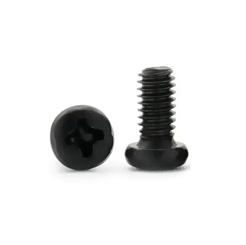
| Screws M2.5×5 mm | 4 | 1,90€ | Aliexpress |
Safety and Important Warnings
⚠️ Never power on the node without an antenna connected. You can permanently damage the LoRa module.
⚠️ Do not power the board via USB and solar/battery at the same time. It may damage your computer’s USB port.
⚠️ If soldering header pins on the LoRa module, make sure the antenna connector doesn’t touch pin 1 (RF output). When mounted directly to the PCB as SMD, this issue doesn’t occur.
Ordering MASN PCBs
You can order the MASN PCBs directly from pcbway.com (the design files are linked in the Bill of Materials).
The process is very simple — just upload the provided files, choose your options, and place the order. I also walk through the process step by step in the following video (Spanish).
Firmware Installation
Before soldering anything, it’s a good idea to make sure the microcontroller works properly and boots without issues. This quick step helps you avoid problems later in the build.
Check or Update the Bootloader
To install the Meshtastic firmware, your microcontroller must have a bootloader version 0.8 or higher. You can check it by following these steps:
- Connect the NiceNano (NRF52840) board via USB.
- Make two quick touches (using metal tweezers) between the RESET and GND pins (see reference photo below) to enter DFU mode.
- Your computer will mount a USB drive named NICENANO or similar.
- Check that the bootloader version is 0.8 or higher. You can verify this by opening the file INFO_UF2.TXT inside the USB drive that appears when entering DFU mode.
- If it is inferior, copy the file update-nice_nano_bootloader-0.9.2_nosd.uf2 into the drive.
- If you need another version, check the official repository.
- After copying, the board will automatically reboot (give it a few seconds).
- If your board doesn’t include a bootloader, follow the official procedure linked in the bootloader guide.
Install the Meshtastic Firmware
- Enter DFU mode (as explained above).
- Open https://flasher.meshtastic.org.
- Select the device NRF52 Pro-micro DIY.
- Choose the latest stable version (or beta if you want to test new features).
- Download the file and drag it into the DFU USB drive.
- Once copied, the board will reboot automatically and start running the Meshtastic firmware.
After this process, you’ll know your microcontroller is healthy and ready to integrate into the node.
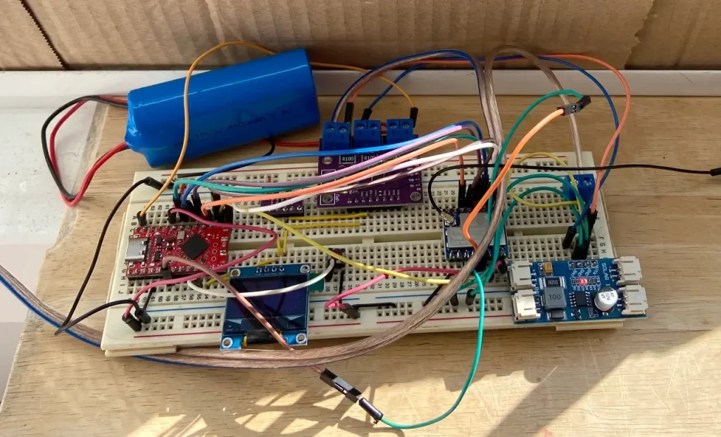
Step-by-Step Assembly
The physical assembly is straightforward if you follow the right order.
The key is to prepare the modules first, then populate the PCB, and finally connect the antenna and power.
Prepare the Modules
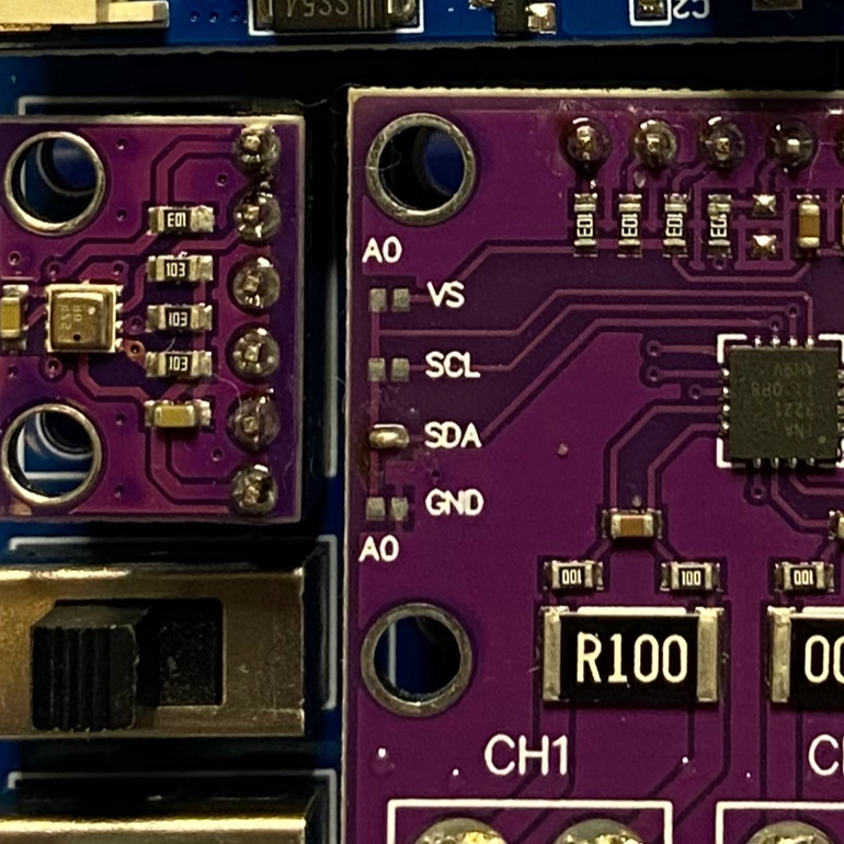
Solder the pins to each module: the temperature sensor, the MPPT charger, the microcontroller, and the LoRa radio module.
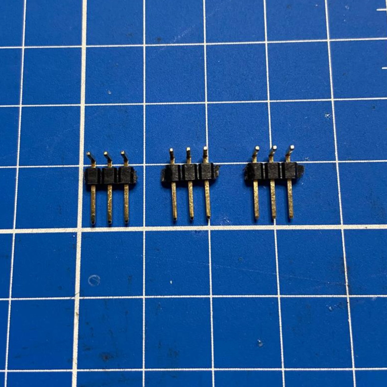
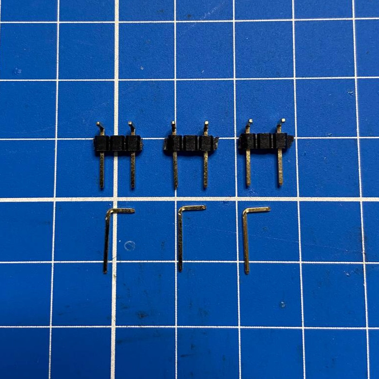
For the INA3221, follow these steps to solder the 90° pins on the channel side and add the SDA bridge.
Step-by-step summary:
- Using the 90° header pins, cut three groups of three pins
- Remove the middle pin with tweezers
- Place the remaining pins in position
- Trim them so they only make contact with the pad
- Solder the pins onto the INA3221 channel pads
- Solder the SDA bridge
Populate the PCB
- Place the modules on the board. You can choose to use female sockets (to make modules swappable) or solder them directly to the PCB.
- Add the buttons, switches, and connectors in their positions.
Prepare the Solar Panel
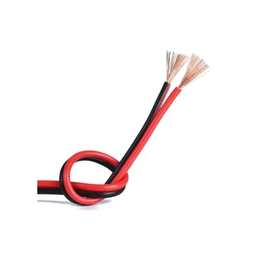
- Remove any factory electronics (LEDs, regulators, etc.) to avoid unnecessary power drain.
- Solder a pair of wires to the terminals and always identify positive and negative — ideally using different wire colors.
Connect Antenna and Power
⚠️ Never power on the node without an antenna connected. You could burn the LoRa module.
- Connect the antenna before powering the system.
- Connect the battery.
- Connect the solar panel (preferably covered while doing so).
After these steps, your node hardware will be fully assembled and ready for configuration.
Basic Meshtastic Configuration
With the hardware ready, it’s time to power up the node (by switching on the toggles) and check that it communicates correctly. For this, we’ll use the official Meshtastic app, available for Android and iOS. You can also use the web version if you prefer.
- Connect to the node via Bluetooth using the app (default PIN: 123456).
- Set the region of use. In the European Union, select EU868 MHz.
- Assign a new Bluetooth PIN for future connections (and make sure to write it down).
- Give your node a short name (4 characters) — this will be its identifier on the mesh network. Example:
CHR3. - In the Telemetry section, enable Power and Environment. This will start transmitting data such as temperature, pressure, current, and voltage.
After saving the changes, the node will begin sending telemetry and will automatically join the network. From the app, you can now check coverage, neighboring nodes, and power consumption.
Remote Control (Remote Admin)
If you plan to leave the node in a remote or hard-to-access location, it’s a good idea to configure it for remote administration. This allows you to change parameters from another node (through the mesh) without needing to plug in a cable or travel to the site.
- Go to the Admin Messages menu and add the private key of one or more of your nodes.
- From that point on, you’ll be able to send configuration commands remotely. These are transmitted as encrypted messages through the mesh network.
By default, for security reasons, nodes only accept commands via USB, Bluetooth, or TCP.
When you enable this option, you expand control capabilities — but use it with caution.
Recommendation: test any configuration change on a test node before applying it to a remote one. That way, you avoid locking yourself out or making the node inaccessible.
Full documentation: https://meshtastic.org/docs/configuration/remote-admin/
Status LEDs and Indicators
INA3221 Current Sensor
VS ONPower is present on the board.PV ONThe enabled channels are detecting valid voltage.
More info: https://done.land/components/power/measuringcurrent/viashunt/ina3221/
MPPT CN3791 Charger
No lightNo sunlight or the panel isn’t providing power.Solid redCharging.Solid blue Batteryfully charged.Fast red blinkingBattery not detected.
More info about the CN3791: Datasheet
NRF52840 Microcontroller
Flashing redThe board is powered and running correctly.
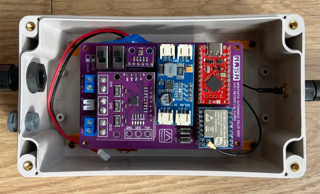
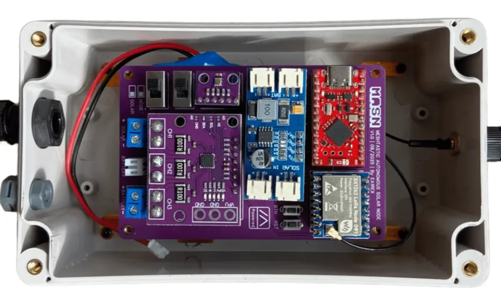
Outdoor Enclosure
To install the node outdoors, proper protection is essential.
The enclosure must be weatherproof, sun-resistant, and allow for some ventilation to prevent condensation and excessive heat buildup.
Choosing the Enclosure
- Use an IP65 or higher electrical box. This is a common standard and provides enough protection against rain and dust.
- The recommended size is 158×90×60 mm, although it depends on your battery and connector layout.
- Material: PVC or ABS. If possible, choose a UV-resistant version.
Antenna
If you want to connect the antenna directly, you can mount the SMA connector on the top of the enclosure. However, if you prefer to use an external pigtail to the antenna, the ideal position is on the bottom side of the box.
Connections
- Cable glands: Essential for routing the solar panel cable while keeping the enclosure sealed.
- Vent plug: Prevents condensation buildup and balances internal air pressure.
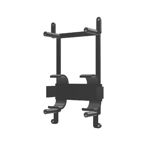
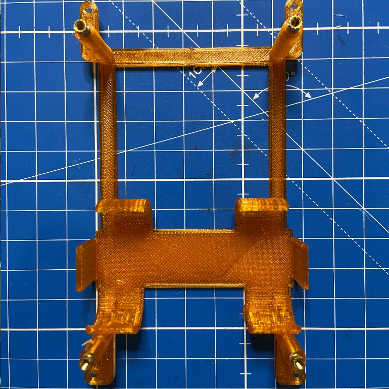
Internal Mounts
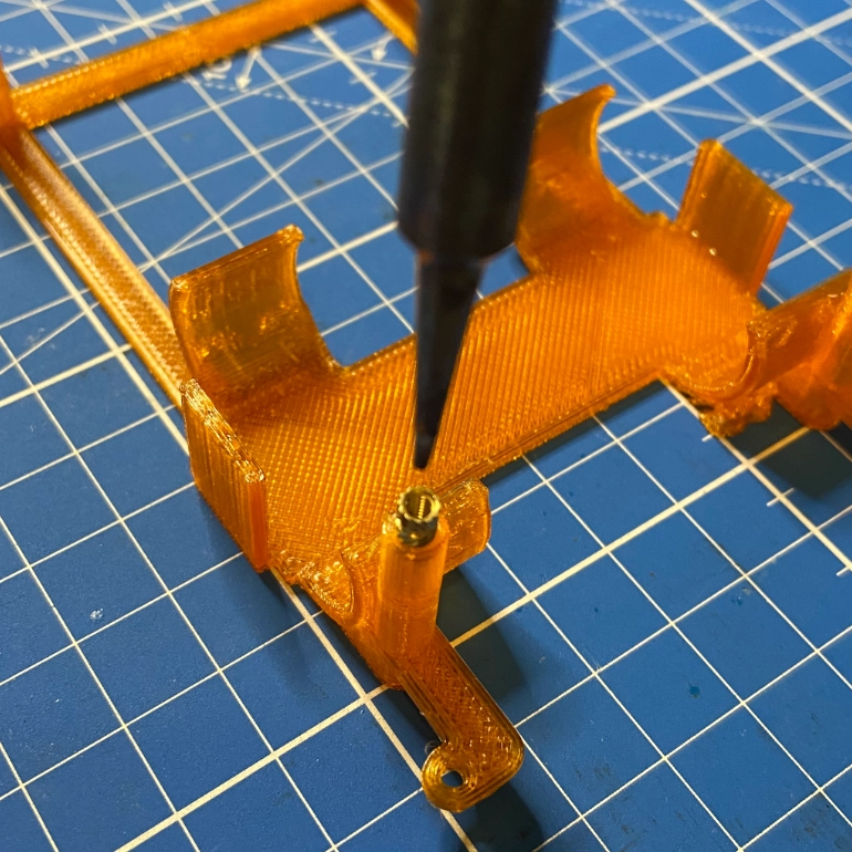
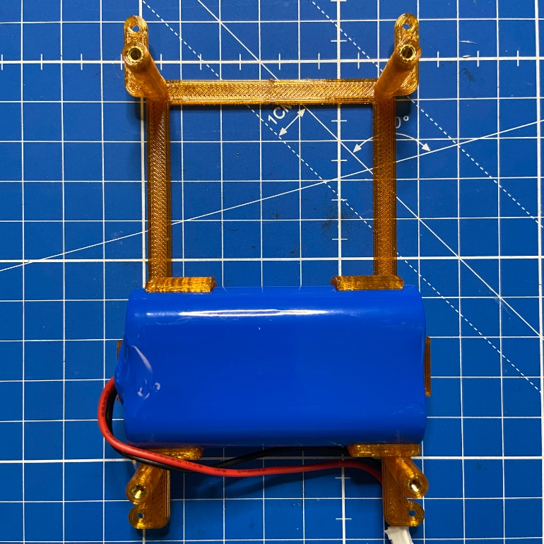
- 3D-print the mounts for the PCB and the battery (links provided in the Bill of Materials). PETG filament is recommended for better temperature resistance.
- Place the threaded inserts into the raised holes.
- Push the inserts in using a soldering iron so they settle into position.
- Position the battery in its mount with the wires facing upward.
Thermal Management
- Interior temperatures can easily exceed 40 °C under direct sunlight.
- Painting the enclosure white or placing it in partial shade helps reduce heat.
- You can also add a small sun shield or mount it on a mast for natural ventilation.
- A practical idea: insulate the battery from the wall of the box that gets the most sunlight. You can use a thin foam sheet or a similar spacer. This keeps the battery cooler and extends its lifespan.
The enclosure doesn’t just protect against rain and dust — it’s also key to the node’s long-term durability. Spending a bit of time choosing and preparing it properly will make a big difference in the project’s lifespan.
Once all the parts are assembled, the enclosure should look like the photo below:
Practical Details and Usage Tips
A few practical details to keep in mind once your node is assembled:
Legal Power Limits
Always respect your region’s regulations.
In Europe, the applicable standard is ETSI EN 300-220, which limits the effective radiated power (EIRP). Using an antenna with too much gain could make your node non-compliant or illegal.
Charging Current
The battery used supports a maximum of 1 A. The MPPT charger can deliver up to 2 A, so you have two options:
- Replace the MPPT shunt resistor with a 0.12 Ω (2512) one to limit the charging current.
- Use a solar panel that doesn’t exceed 1 A of output current.
Nighttime Leakage
The suggested CN3791 MPPT charger doesn’t include a blocking diode, so you’ll see a small negative current (~2 mA) flowing toward the panel at night. That equals about 24 mAh/day, or roughly 0.6% of a 4000 mAh battery — negligible in practical use.
License: CERN OHL-S v2
MASN is an open and free hardware project, licensed under the CERN Open Hardware Licence Version 2 – Strongly Reciprocal (CERN OHL-S v2).
This means you can use, manufacture, modify, and share this design freely, even for commercial purposes — as long as you keep the same license and publish any modifications you make.
The goal is to ensure that knowledge and improvements remain accessible to everyone, fostering an open, collaborative, and transparent ecosystem.
Acknowledgments
Thanks to everyone who contributed ideas, tested prototypes, and shared feedback during our meetings in A Coruña and the Bricolabs group, which came together to move this project forward. Special thanks to EA3GRN for his videos and to the fakeTec project, which served as the foundation for this work. Also, heartfelt appreciation to the Meshtastic España community for their support, resources, and active involvement in improving and spreading the project.
Additional thanks to PCBWay, who contacted us and are collaborating with the project by providing free PCBs for our prototype iterations, making faster experimentation and open development possible.
Disclaimer
This project is shared as is, without warranty. Each person is responsible for assembling and using their own node. If you decide to deploy it, make sure you comply with your region’s radio regulations.