I tripled my UPS battery capacity: Was it worth it?

From 7Ah to 22Ah to protect my NAS, keep the internet running during power cuts, and discover that 0% on a UPS does not always mean 0%.
For a while, I used an Eaton Ellipse ECO 650 UPS to protect my NAS. The idea was simple: if the power went out, the UPS had to give it enough time to shut down properly and prevent data problems.
The problem was that the original battery had become badly degraded. During the latest outages, the UPS lasted only a short time, which is a poor combination for a NAS.
I had already experienced data corruption after an abrupt shutdown and had to spend several days restoring the system. Since then, having a UPS that actually works has stopped being “an extra” and has become an important part of my setup.

Value 4 value⚡️
If the content has been useful to you, please consider supporting me so that I can create more articles like this. Lightning address (only for Lightning payments): [email protected]
What finally convinced me was an eight-hour power cut. The fibre connection was still working, but my router, modem and NAS ran out of power very quickly.
To make matters worse, Spain were playing that day. With the 4G connection performing poorly, I ended up watching only parts of the match. It was not the end of the world, but it was the perfect reminder that, if the fibre network remains active during an outage, it makes a lot of sense to keep at least the modem and router running.
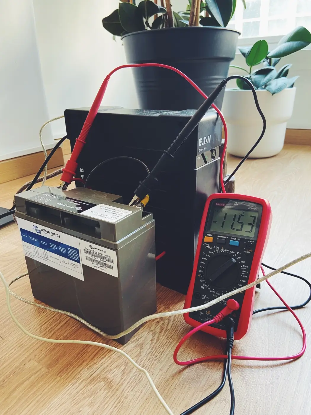
So I decided to run an experiment: keep the same UPS, but replace its original 12V 7Ah battery with a 12V 22Ah Victron AGM battery.
The question was quite simple: would I gain real runtime, or would the UPS shut down anyway because it “thinks” it still has the original battery?
Before you begin: an important warning
This modification is neither official nor approved by Eaton. The Eaton Ellipse ECO 650 is designed to work with a specific battery. Although that battery is replaceable, the manufacturer does not present this model as a UPS with extended battery capacity.
⚠️ Warning: this project involves high currents at 12V and a UPS that operates internally at 220V. If you do not have at least a basic understanding of electricity, polarity, fuses, insulation and cable sizing, do not copy this blindly.
For this project, I did not modify the 220V section of the UPS. The modification was made on the battery side, but that does not mean it is risk-free. A 12V AGM battery can deliver extremely high currents in the event of a short circuit.
At 12V, you do not face the same electric-shock risk as at 220V, but you can still get sparks, overheating cables, damaged terminals or even a fire if the installation is done incorrectly. That is why I used appropriately sized cable, short cable runs, crimped terminals and a fuse on the battery’s positive lead.
This article explains what I did, my calculations and my results. It is not an invitation to modify a UPS without knowing what you are doing.
The goal of the project
My goal was not to get more power from the UPS. The Eaton Ellipse ECO 650 is still a small UPS with a rated output of 650VA / 400W. Replacing the battery does not make its internal electronics more powerful.
What I wanted was more runtime with small loads. In my case, the main goal was to allow the NAS to shut down correctly and then keep the router and modem running for several hours.
There is also a secondary use that I find quite interesting: during a real power cut, this modified UPS can also work as a small emergency energy reserve. If the load is managed carefully, it can charge a phone, power a low-consumption LED light or run another small device for a limited time.
It is not a portable power station or a battery capable of powering half a house, but it can still make a real difference during a long outage. Being able to charge a phone, keep the internet running or use a basic light for a few hours can be far more useful than it sounds when the power actually goes out.
The equipment I wanted to protect
The plan was to power the following equipment during an outage:
| Equipment | What it should do during the outage |
|---|---|
| NAS | Shut down automatically after 2 minutes |
| Router | Keep running |
| Modem/ONT | Keep running |
| Local network | Remain available |
| Fibre connection | Keep working if the external network remains active |
| Phone / LED light / small device | Occasional use if needed |
The NAS is the device I am most concerned about protecting, but I do not need it to remain on for hours. What matters is that it detects the outage, waits for a short grace period and shuts down correctly.
After that, the UPS only needs to keep the router and modem/ONT running. If the outage continues, it can also be used to charge a small device, provided that any additional load will reduce the total runtime.
The idea: more battery capacity, not more power
The original battery in this UPS is rated at 12V 7Ah. The battery I used for the experiment was a 12V 22Ah Victron AGM.
12V × 7Ah = 84Wh
12V × 22Ah = 264Wh
On paper, the new battery has slightly more than three times the nominal capacity of the original one.
22Ah / 7Ah = 3.14However, this does not mean that the UPS becomes three times more powerful. It means that, in theory, it can provide more runtime if the load is reasonable.
Key idea: a larger battery is like a larger fuel tank. It gives you more runtime, but it does not turn the UPS into an industrial unit.
That is why this project makes sense for small loads, such as a NAS during shutdown, a router, a switch or a modem. I would not treat it as a way to run the UPS at 400W for hours, because the internal electronics remain unchanged.
Materials used
These are the main materials I used for the modification. I am leaving the links in place because I want to add affiliate links or links to the specific products I actually purchased.
| Material | Qty | Purpose | Link |
|---|---|---|---|
| Victron AGM 12V 22Ah battery | 1 | Replace the original 7Ah battery | Amazon |
| Battery terminal covers | 2 | Protect the battery terminals | AliExpress |
| Red AWG10 cable | 1m | Connection between the UPS and battery | TME |
| Black AWG10 cable | 1m | Connection between the UPS and battery | TME |
| MIDI fuse holder | 1 | Fuse on the battery’s positive lead | TME |
| 30A MIDI fuses | 2 | Short-circuit protection and current limiting | TME |
| 6.3mm insulated male Faston terminals | 5 | Connection to the UPS | TME |
| M8 ring terminals | 5 | Connection to the battery terminals | TME |
| M5 ring terminals | 5 | Connect cables to the fuse holder | TME |
| Crimping tool for insulated terminals | 1 | Crimp terminals correctly | TME |
| Heat-shrink tubing | 1m | Additional insulation | TME |
| Multimeter | 1 | Check polarity and voltage | Amazon |
Safety: why I used AWG10 cable and a 30A fuse
An important part of the project was doing the calculations before connecting anything. When working at 12V, currents can become very high even when the power on the 220V side seems modest.
For example, an 80W load at the UPS output requires approximately the following current from the battery, assuming an inverter efficiency of around 85%:
80W / 0.85 / 12V ≈ 7.8AThat is still a reasonable current. However, if someone tried to operate the UPS close to its 400W maximum, the situation would change considerably:
400W / 0.85 / 12V ≈ 39AIf the battery voltage falls during discharge, for example to 10.5V, the current would be even higher:
400W / 0.85 / 10.5V ≈ 45AThat is why I used AWG10 cable, very short cable runs and a 30A fuse on the 12V side.
The 30A fuse
The fuse is installed on the battery’s positive lead, as close to the battery as possible. The idea is that, if there is a short circuit or another serious fault, the fuse should blow before the cable, terminals, battery or UPS are damaged.
With a 30A fuse at 12V, the theoretical DC power limit would be:
12V × 30A = 360W DCInverter losses then have to be taken into account. At an approximate efficiency of 80–90%, that would correspond to roughly the following AC output:
360W × 0.80–0.90 = 288–324W ACEven so, I would not treat that figure as a continuous operating limit. For this modification, my cautious limit would be around 200–250W AC maximum, and my real-world use is far below that.
My rule: the fuse should fail before the cable, terminals, battery or UPS.
General installation
I am not presenting this as a universal guide to opening any UPS. Every model can be different, and a UPS contains areas that operate at 220V. If you cannot identify what you are touching, you should not be touching it.
In my case, the modification focused on replacing the original battery with a higher-capacity external battery while retaining the existing 12V connection used by the UPS.
The general wiring arrangement was:
UPS positive → 30A fuse holder → battery positive
UPS negative → battery negative
The fuse is fitted on the positive lead, close to the battery. It is also essential to check polarity with a multimeter before connecting anything, because reversing the polarity on a UPS can end very badly.
General steps
- Disconnect the UPS from the mains supply.
- Switch off the UPS.
- Remove the original battery.
- Identify the polarity and connector type.
- Prepare the AWG10 cables, keeping them as short as possible.
- Crimp the terminals correctly.
- Install the fuse holder on the positive lead.
- Connect the external battery.
- Check polarity and voltage with a multimeter.
- Insulate the connections and protect the battery terminals.
- Charge the battery.
- Run an initial short test with a small load.
- Run a real-world runtime test.
One important detail: the battery terminals should not be left exposed. Any metal object falling across the positive and negative terminals could cause a serious short circuit.
Removing the battery from an Eaton Ellipse ECO 650
The strange part: the UPS still thinks it has a 7Ah battery
The Eaton Ellipse ECO has a USB port. It reports information to a computer or NAS, including the UPS status, whether it is charging or running on battery, the remaining percentage and the estimated runtime.
The problem is that these calculations appear to be designed for the original battery. After fitting a 22Ah battery, the UPS does not actually “know” that it has a larger battery.
I discovered this during testing. The reported percentage began falling very quickly—far faster than made sense when compared with the battery’s actual voltage.
The big question was:
Will the UPS shut down when USB reports 0%, even though the battery still has energy left?
If the answer was yes, the larger battery would be of little use. If the answer was no, the indicator would be unreliable, but the additional runtime could still be used.
Real-world runtime test
For the test, I used a simple and stable load: two 40W incandescent light bulbs, giving a total load of approximately 80W.
I chose incandescent bulbs because they are a predictable resistive load. They contain no unusual electronics, no motors and do not introduce strange power spikes. That makes a runtime test much simpler.
I also connected the UPS to a Mac via USB to record the information reported by the system. This was the script:
caffeinate -dimsu &

while true; do
  fecha="$(date '+%Y-%m-%d %H:%M:%S')"
  linea="$(pmset -g ps | grep 'Ellipse ECO')"

  if [ -z "$linea" ]; then
    echo "$fecha | UPS_NOT_PRESENT"
  else
    echo "$fecha | $linea"
  fi

  sleep 10
done | tee ~/Desktop/ups-test.txt
This script does not measure the battery’s actual voltage. It only records what the UPS reports over USB. I used a multimeter for the voltage and wrote down the readings manually.
Manual voltage measurements
| Time | Battery voltage | Status |
|---|---|---|
| 08:18 | 13.71V | UPS connected to mains power |
| 08:23 | 12.51V | Disconnected for several minutes |
| 08:32 | 12.48V | Discharging |
| 09:00 | 12.27V | Discharging |
| 09:22 | 12.06V | Discharging |
| 10:41 | 11.46V | UPS already switched off |
It was not a perfect data-logging system, but it was sufficient to understand what was happening.
Test results
According to the log, the UPS started running on battery at 08:19:39. The first record where it no longer appeared as present was at 10:31:05.
08:19:39 → 10:31:05 = 2h 11m 26sWith an 80W load, the approximate usable energy was:
80W × 2.1905h ≈ 175WhThe battery’s nominal capacity is:
12V × 22Ah = 264WhThe approximate usable energy at the AC output was therefore:
175Wh / 264Wh ≈ 66%That 66% should not be interpreted as the inverter’s “pure efficiency”. It combines the UPS’s internal losses, its own power consumption, the AGM battery’s behaviour under load, voltage drop and the point at which the UPS decides to shut down.
For a real-world test, I consider the result quite reasonable.
Result: with an 80W resistive load, the UPS ran for approximately 2 hours and 11 minutes.
When the test is complete, remember to terminate the caffeinate process:
pkill caffeinateThe 0% that was not really 0%
The most interesting part of the test was what happened with the percentage reported over USB.
The UPS eventually reported:
0%; discharging; 0:00 remainingat 08:55:25.
However, it did not shut down. It continued powering the bulbs until approximately 10:31:05.
08:55:25 → 10:31:05 = 1h 35m 40sIn other words, the UPS continued running for more than an hour and a half after reporting that the battery was at 0%.
This confirms two important points. First, the percentage reported over USB is not reliable with a modified battery. Second—and much more positively—the UPS does not shut down automatically simply because the software reports 0%.
In my case, that was exactly what I wanted to establish. The indicator had completely lost track of the real capacity, but the UPS continued delivering power.
Comparison with the original 7Ah battery
The original 7Ah battery has an approximate nominal energy capacity of:
12V × 7Ah = 84WhThe 22Ah Victron battery has:
12V × 22Ah = 264WhIf we scaled the real test linearly, the result would be:
2h 11m 26s × 7/22 ≈ 41–42mHowever, that would be an idealised calculation. At 80W, a 7Ah battery is under considerable stress because the approximate current on the 12V side would be:
80W / 0.85 / 12V ≈ 7.8AThat is roughly a 1C discharge rate for a 7Ah battery. At that rate, the usable capacity of a lead-acid battery falls significantly.
For that reason, with a new original battery, I would expect something closer to:
| Battery | Expected runtime at 80W |
|---|---|
| New 12V 7Ah | 25–40 minutes |
| 12V 22Ah Victron | 2h 11m measured |
If the original battery were old, the runtime would be considerably shorter. That was precisely my original problem.
My real-world use: NAS, router and modem
The 80W test provides a useful reference, but my actual load is different.
My setup includes:
- NAS
- 3 mechanical hard drives
- 1 SSD
- Docker with several running containers
- Router
- Modem/ONT
The NAS is configured to shut down 2 minutes after detecting a power cut. This matters because the NAS can consume considerably more power than the router and modem, but it will only remain on for a very short time.
Power figures used for the calculation
| Equipment | Power consumption used |
|---|---|
| NAS | 28.8W during access, according to the specification sheet |
| Router | 15W maximum without accessories |
| Modem/ONT | Less than 13W |
| SSD | Up to 3.6W while writing |
| Mechanical hard drives | Drive consumption included in the NAS estimate |
In my setup, the router has no devices connected over PoE or USB. The modem/ONT has Wi-Fi disabled, but I used the conservative figure of less than 13W because I do not have a separate official figure for that mode.
Because the NAS contains hard drives, an SSD and Docker containers, I prefer to use a practical range:
NAS with drives + Docker: 35–45WIt is not an exact official figure, but I consider it reasonable for a calculation that includes some margin.
Phase 1: the first 2 minutes of the outage
During the first 2 minutes, everything would remain on:
NAS:         35–45W
Router:      up to 15W
Modem/ONT:   up to 13W
Total:       63–73W
Even using the upper figure of 73W, the energy consumed over 2 minutes is small:
73W × 2/60h ≈ 2.4WhCompared with the 175Wh of usable energy measured during the test, those 2 minutes of NAS operation barely affect the total runtime.
The NAS is important, but it does not determine how long the complete system will run if it shuts down promptly.
Phase 2: after the NAS shuts down
After the NAS has shut down, the router and modem/ONT remain running:
Router:      15W
Modem/ONT:   13W
Total:       28W
Using the usable energy measured during the test:
175Wh / 28W ≈ 6.25hI would not treat that number as an exact promise. At low loads, the UPS also has its own internal power consumption, and runtime does not scale perfectly.
However, as a practical estimate:
| Scenario | Expected runtime |
|---|---|
| Conservative | 5 hours |
| Realistic | 5.5–6.5 hours |
| Optimistic | 6–7 hours |
For planning purposes, I am using 5 hours as a safe figure. If it lasts longer, even better.
It also works as a small emergency energy reserve
Although the main goal was to protect the NAS and keep the internet running, there is another important use: during a real power cut, this modified UPS can also serve as a small emergency energy reserve.
I am not suggesting connecting large loads or using it as though it were a portable power station. However, if it is managed carefully, it can handle specific tasks: charging a phone, powering a small LED light, running a laptop for a while or supplying another low-consumption device for a limited period.
The key is to remember that every additional load reduces the runtime. If the router and modem consume around 28W and I also connect a 10W phone charger, the total load becomes approximately:
28W + 10W = 38WUsing the usable energy measured during the test:
175Wh / 38W ≈ 4.6hThis means that charging a phone is perfectly possible, but it is not free. If I connect several devices at once, the runtime falls.
Some approximate examples:
| Additional use | Approximate consumption | Impact |
|---|---|---|
| Charging a phone | 5–15W | Low |
| Small LED light | 5–10W | Low |
| Charging a tablet | 10–20W | Medium |
| Lightweight laptop | 30–60W | High |
| Space heater, hair dryer or microwave | Hundreds of watts | Not recommended |
During a long outage, the sensible approach would be to prioritise. First, let the NAS shut down correctly. Then keep the router and modem running. If necessary, use the UPS occasionally to charge phones or power an LED light.
Key idea: this modification does not turn the UPS into a battery for everything, but it does make it a useful energy reserve when managed sensibly.
For me, this is one of the most interesting parts of the project. I have not only gained protection for the NAS; I have also gained extra time to stay connected during a power cut.
What I would not do with this modified UPS
I would not use this modification to power large loads for long periods. The battery is larger, but the UPS electronics remain unchanged.
I would especially avoid:
- space heaters
- hair dryers
- microwaves
- refrigerators
- laser printers
- motors
- power tools
- loads close to 400W for long periods
I would also avoid thin cables, removing the fuse or leaving the battery terminals exposed. If the battery were positioned far from the UPS, the cable size, voltage drop and protection would need to be recalculated.
⚠️ Practical limit: although the UPS is rated at 400W, I designed this modification for small and medium loads. In my setup, the real load will be well below 100W after the NAS shuts down.
Safety label
One thing I intend to do is attach a physical label to the UPS or place one nearby. It may seem unnecessary, but after a few months or years, it is easy to forget the exact limits of a modified installation.
A useful label could say:
MODIFIED UPS

External battery: AGM 12V 22Ah
DC fuse: 30A
Cable: AWG10
Recommended continuous AC limit: 200–250W
Intended use: NAS + router + modem/ONT
Do not connect heating loads, motors or laser printers
Do not rely on the USB battery percentage
It also makes sense to keep a small information sheet with the wiring diagram, the installed fuse rating, the cable size, the test date and the measured runtime.
It is not corporate documentation. It is a note to stop my future self from doing something stupid.
Was it worth it?
For my use case, yes.
With an 80W resistive load, the UPS ran for 2 hours, 11 minutes and 26 seconds. That is far longer than I would expect from the original 7Ah battery, even if it were new.
I also confirmed something important: the battery percentage reported over USB cannot be used to estimate the real runtime with this battery. The UPS reached 0% very quickly, but continued running for more than an hour and a half.
In my real-world setup, the NAS will shut down after 2 minutes and the UPS will then only need to power the router and modem. Based on the calculated consumption, I conservatively expect around five hours of runtime, and possibly more.
If I manage it carefully, I can also use it as a small emergency energy reserve to charge a phone, power an LED light or keep another small device running during a long outage. It is not a battery for everything, but it is a practical help when the power genuinely goes out.
It is not an official modification. It is not for everyone. And I would not use it for large loads.
For protecting my NAS, keeping the internet running and providing basic backup power during outages, the upgrade has worked extremely well.