MASN V2.0: the Meshtastic solar node is now more resilient
MASN V2.0 is an evolution of the original MASN PCB, developed to improve the reliability of the Meshtastic solar node in real-world, long-term outdoor installations.
The first version of the project was focused on simplifying the assembly of an autonomous solar node by reducing wiring, integrating the main modules into a single PCB, and using components that are easy to solder. That version remains valid and continues to be the recommended option for users looking for a simple build based mainly on THT components.
Version 2.0 keeps the same general philosophy of the project, but introduces two important improvements: battery level reading from Meshtastic and a voltage supervision system to improve the node’s behavior when the battery is fully depleted.
These improvements address issues detected during real-world use of the board in autonomous solar nodes. In particular, work has focused on the system’s behavior when the battery is protected by the BMS and the solar panel begins to deliver voltage progressively as it receives the first hours of daylight.

Value 4 value⚡️
If the content has been useful to you, please consider supporting me so that I can create more articles like this. Lightning address (only for Lightning payments): [email protected]
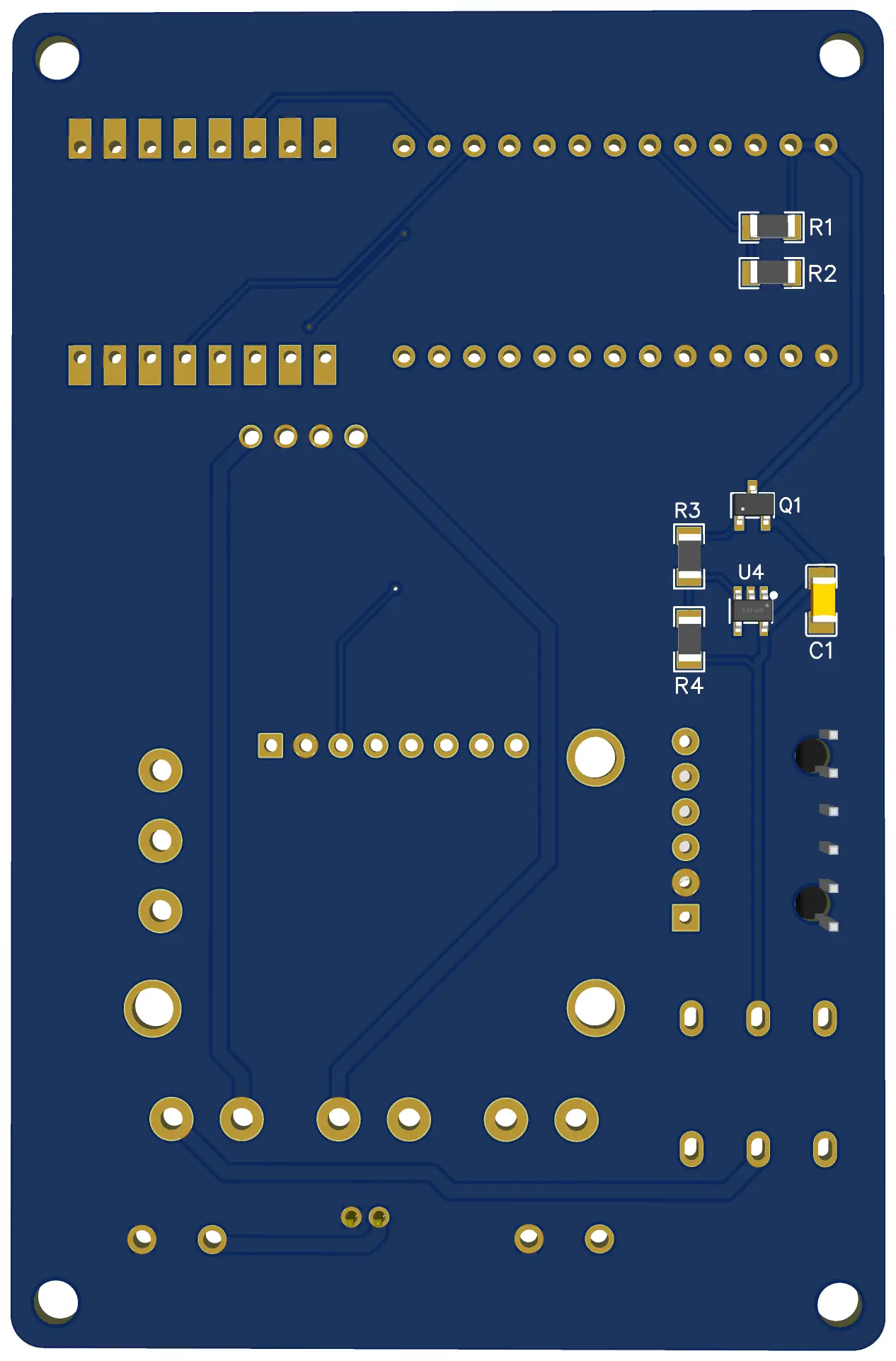
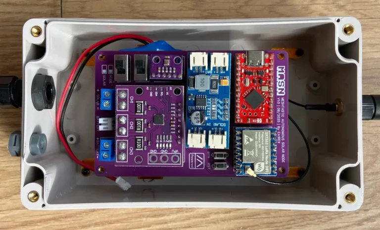
Unlike the previous version, MASN V2.0 includes some SMD components. This makes it possible to add new functions without significantly increasing the size of the PCB, although it also makes assembly more difficult.
For this reason, MASN V1 remains the easiest version for getting started with the project, while MASN V2.0 is aimed at those looking for a more complete, more resilient board that is better prepared for remote or hard-to-access installations.
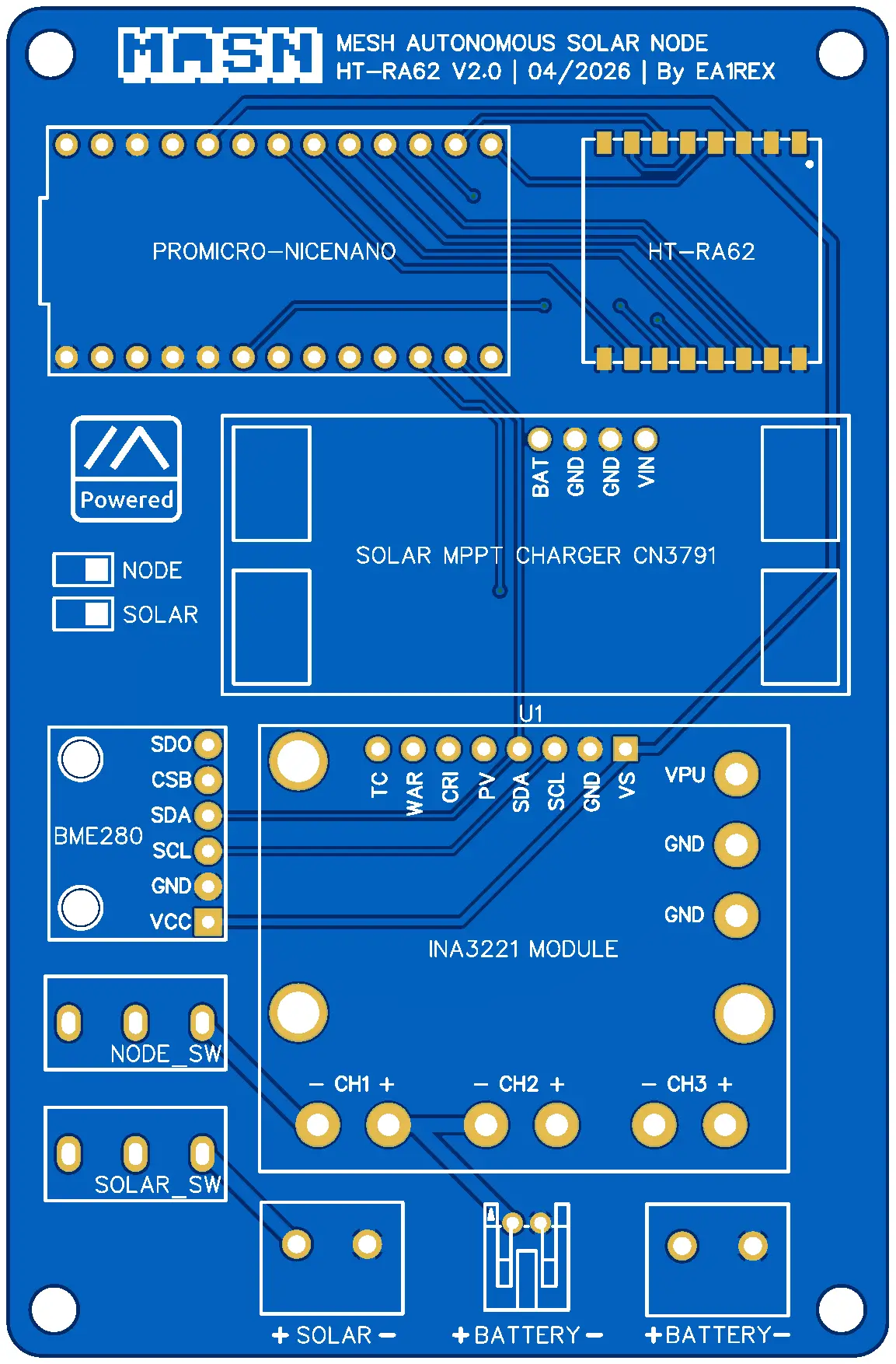
Changes compared to MASN V1
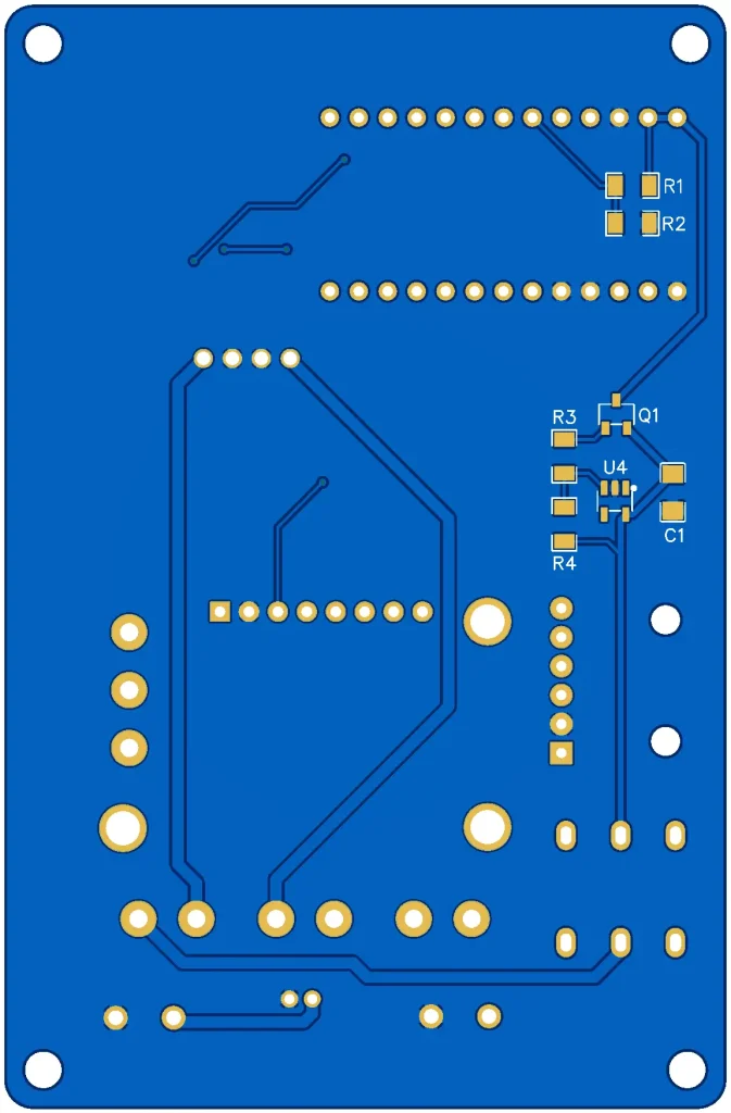
At the design level, MASN V2.0 keeps the general structure of the original board, but adds a small electronic stage intended to improve the node’s power management.
The main practical difference is that the new version no longer relies solely on the behavior of the microcontroller and the battery BMS during low-voltage situations. The board incorporates additional components to better handle those states and avoid incomplete startups.
The circuitry required for the battery voltage to be read directly by the NRF52 has also been added. This allows the Meshtastic app to display the node’s battery status in the device list.
| Aspect | MASN V1 | MASN V2.0 |
|---|---|---|
| Assembly | THT components | THT + SMD |
| Difficulty | Easier | Moderate |
| Battery reading in Meshtastic | Not directly available | Added through a voltage divider |
| Low-voltage protection | Dependent on system behavior | Added through a voltage supervisor |
| Recommended use | First build, learning, testing | Outdoor or remote installations |
Battery level reading in Meshtastic
One of the improvements introduced in MASN V2.0 is battery voltage reading from the NRF52 microcontroller.
To achieve this, a voltage divider has been added and connected to an analog input on the microcontroller. This circuit adapts the battery voltage to a safe range for the NRF52, allowing Meshtastic to interpret that value as the node’s battery information.
This improvement does not replace the telemetry provided by the INA3221. The INA3221 remains useful for checking voltages and currents in different parts of the system, such as the solar panel, the MPPT charger output, or the node’s power consumption.
The main difference is its integration within Meshtastic. With MASN V2.0, the battery level can be shown in the general node list of the application, alongside the other devices in the network.
This makes it easier to check the node’s status at a glance, especially when it is installed outdoors or in a hard-to-access location. It does not add a completely new measurement to the system, but it does make the battery information more visible and easier to check from Meshtastic’s usual interface.
Voltage supervisor and recovery after full discharge
During testing and real-world use of MASN V1, a specific behavior was detected in some nodes powered by battery and solar panel.
When the battery was fully discharged, the BMS cut off the output to protect it. In that state, the node shut down correctly. The problem could appear later, when the solar panel started receiving light and generated an initial voltage that was still too low to power the system reliably.
Under those conditions, the NRF52 could attempt to start before the power supply was adequate. This incomplete startup could leave the microcontroller in an unstable state, known as brownout, from which it would not always recover without a manual reset.
MASN V2.0 incorporates a voltage supervisor to avoid this scenario.
Its function is to keep the system disconnected while the voltage has not reached a safe level. When the power supply is back within the proper range, the node can perform a clean startup.
This modification is especially useful for the node’s behavior during real solar charging cycles, where voltage does not appear instantly, but progressively depending on available light, panel orientation, battery state, and environmental conditions.
The goal of this improvement is to reduce the possibility of a remote node becoming locked up after a deep battery discharge.
Available MASN V2.0 variants
MASN V2.0 is available in two variants, depending on the LoRa radio module used.
| PCB variant | LoRa module |
|---|---|
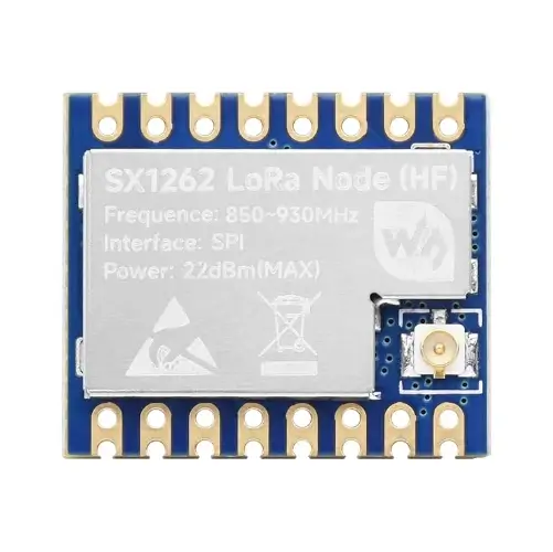
| MASN Core1262 V2.0 | Waveshare Core1262 HF |
| MASN HT-RA62 V2.0 | HT-RA62 |
Both variants include the same MASN V2.0 improvements. The difference lies in the format and pinout of the LoRa module, so it is important to choose the correct PCB before ordering it.
Assembly considerations
MASN V2.0 keeps a similar assembly process to the previous version for most of the main components. The modules, connectors, push buttons, and switches are still placed directly on the PCB.
The main difference is the addition of several SMD components associated with the new battery reading and voltage supervision functions. These components require more precise soldering than the usual THT parts.
For this version, the following tools are recommended:
| Tool | Recommended use |
|---|---|
| Soldering iron with a fine tip | Soldering small components |
| Flux | Improves SMD soldering quality |
| Precision tweezers | Placing resistors, capacitors, and the supervisor |
| Magnifying glass or simple microscope | Visual inspection of solder joints |
| Multimeter | Checking continuity and voltages before powering the board |
Before connecting the battery or solar panel, it is advisable to inspect all SMD solder joints and check that there are no bridges between nearby pads. It is also recommended to verify continuity on the main power lines.
The assembly does not require advanced equipment, but it does require more attention than MASN V1. For this reason, this version is better suited for users who already have some soldering experience or who can get help during assembly.
If you do not want to solder the SMD components manually, you may consider ordering the PCB with those components already assembled by the manufacturer. This option simplifies the assembly process, although it increases the final cost of the order.
Bill of materials (BOM)
The electronics of MASN V2.0 are built from a series of modules and components detailed below.
Since some purchase links may stop working over time, reference photos of each component are also included. This makes it easier to identify them and search for them from other sellers if necessary.
You can install the PCB in any waterproof enclosure compatible with the size of the board, the battery, and the solar panel you plan to use.
MASN V2.0 components for the Core1262 module
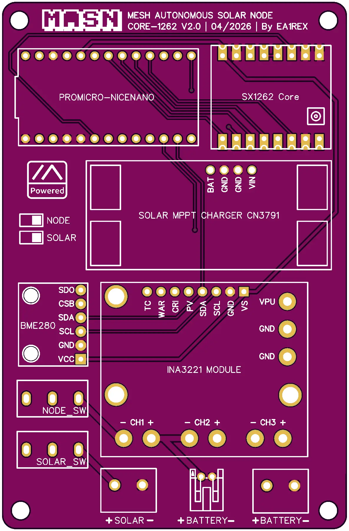
| Part | Qty. | Cost | Source | Notes |
|---|---|---|---|---|
| MASN V2.0 PCB for Core1262 | 1 | €5 | Download | |
| Waveshare Core1262 HF LoRa module | 1 | €8.79 | Aliexpress | Choose the 868 MHz version if you are in Europe |
MASN V2.0 components for the HT-RA62 module
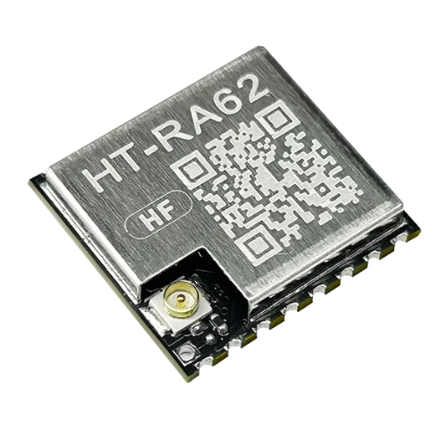
| Part | Qty. | Cost | Source |
|---|---|---|---|
| MASN V2.0 PCB for HT-RA62 | 1 | €5 | Download |
| HT-RA62 LoRa module | 1 | €5.29 | Aliexpress |
Components shared by both variants
| Ref | Part | Qty. | Cost | Source | Notes |
|---|---|---|---|---|---|
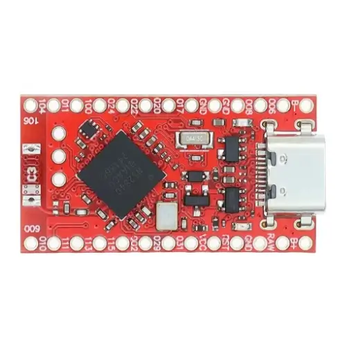
| NiceNano (NRF52840) | 1 | 3€ | Aliexpress | Get the red PCB version | |
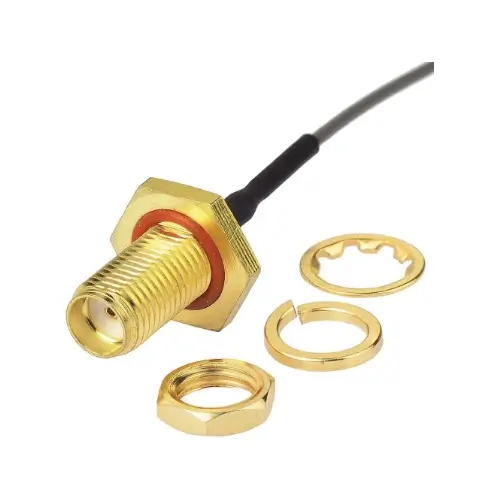
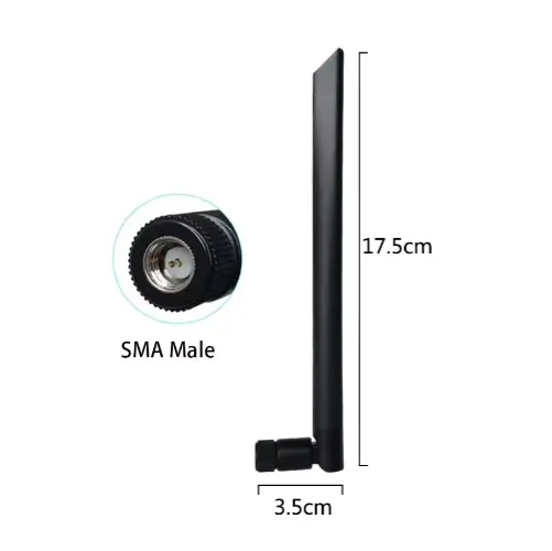
| Antenna Cable UFL to SMA | 1 | 2€ | Aliexpress | 15 cm female version | |
| GrandWisdom 868 MHz Antenna | 1 | 3,40€ | Aliexpress | SMA male connector | |
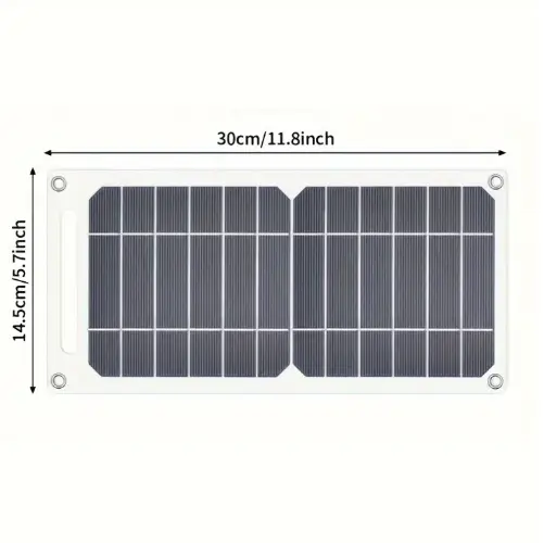
| 5V Solar Panel | 1 | 6,89€ | Aliexpress | Claims 35 W, but not real | |
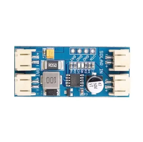
| MPPT CN3791 Charger | 1 | 2,20€ | Aliexpress | Select the 6V version | |
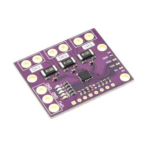
| INA3221 Current Sensor | 1 | 1,72€ | Aliexpress | Buy the purple one, not the black | |
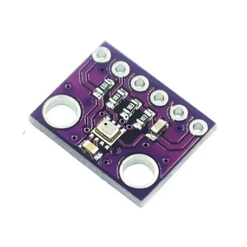
| BME280 Temperature/Humidity Sensor (GY-BME280-3.3) | 1 | 0,94€ | Aliexpress | Choose 6-pin, 3.3 V version | |
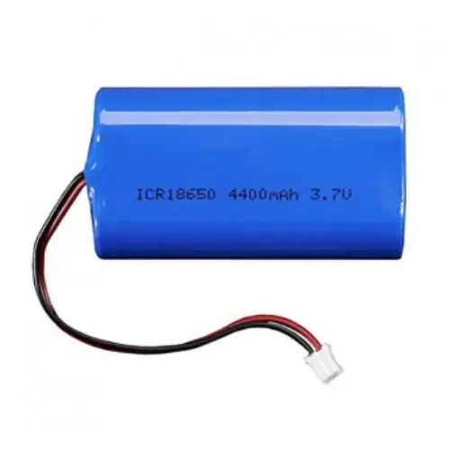
| Li-ion Battery 4400 mAh / 3.7 V | 1 | 10€ | Aliexpress | With PH2.0 connector and BMS (Battery Management System) | |
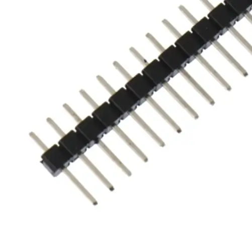
| 40-pin Straight Headers 2.54 mm | 2 | 1,4€ | Aliexpress | ||
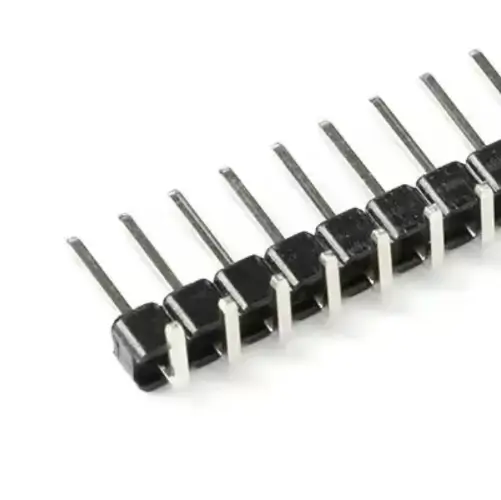
| 40-pin 90° Headers 2.54 mm | 1 | Aliexpress | |||
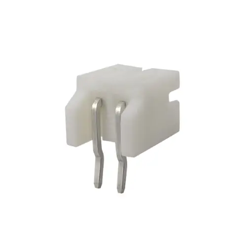
| 2P JST PH 2.0 mm Battery Connector | 1 | 1,62€ | Aliexpress | ||
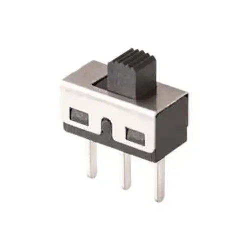
| SS12D10 Switches | 2 | 0,99€ | Aliexpress | ||
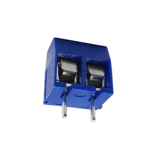
| 2P Screw Terminals for Battery/Solar | 2 | 1,80€ | Aliexpress | ||
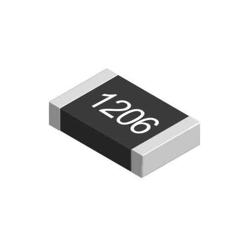
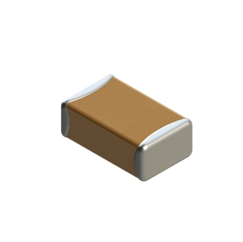
| R1, R2 | SMD resistor 1 MΩ – 1206 | 2 | 4,59€ | Aliexpress | Buy the 1206 kit; it includes several values. |
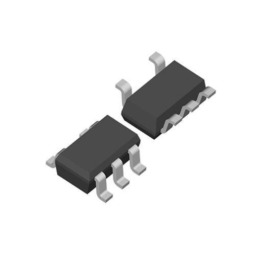
| U4 | SMD voltage supervisor MCP1321T-29LE/OT – SOT-23 | 1 | 0,85€ | TME | |
| C1 | SMD capacitor 100 nF – 1206 | 1 | 4,59€ | Aliexpress | Buy the 1206 kit; it includes several values. |
| R4 | SMD resistor 680 kΩ – 1206 | 1 | 0 | Aliexpress | Already included in the previous kit. |
| R3 | SMD resistor 200 Ω – 1206 | 1 | 0 | Aliexpress | Already included in the previous kit. |
| Q1 | SMD transistor AO3407A – SOT-23 | 1 | 0,85€ | TME | Comes in a pack of 5 units. |
Schematics and files
The schematics and manufacturing files for MASN V2.0 are included below.
The board is available in two variants, depending on the LoRa module used. Before ordering the PCB, make sure you are downloading the files that correspond to the module you are going to assemble.
SMD component references
The SMD components added in MASN V2.0 are: R1 = 1 MΩ, R2 = 1 MΩ, R3 = 200 Ω, R4 = 680 kΩ, Q1 = AO3407A, C1 = 100 nF, and U4 = MCP1321T-29LE/OT.
Before manufacturing or assembling the board, always check these values against the corresponding schematic.
Dimensions and mounting
- PCB size: 63.4 mm x 96.9 mm
- Mounting holes: 56.7 mm x 90 mm
MASN V2.0 schematic diagram for Core1262
MASN V2.0 schematic diagram for HT-RA62
Ordering MASN V2.0 PCBs
You can order the PCBs directly from pcbway.com, which collaborates with the project by providing boards for the prototyping iterations.
PCBWay allows you to upload the Gerber files, review the board preview, and manufacture the PCBs without needing to modify advanced parameters. For this project, the default settings are usually sufficient.
The following video shows the complete process for ordering MASN V2.0 PCBs from PCBWay.
In addition to ordering only the PCB, it is also possible to request assembly of the SMD components directly from the manufacturer.
This option can be useful if you do not have experience soldering SMD components or if you want to assemble several boards more conveniently. In that case, the manufacturer takes care of soldering the specified components during the manufacturing process.
Keep in mind that this option increases the final cost of the order. In addition to the PCB cost, the components, assembly service, and, in some cases, additional setup costs are added.
To request this type of assembly, additional files are usually required, such as the specific bill of materials for assembly and the component position file. For this reason, make sure you are using the correct MASN V2.0 files and the correct board variant.
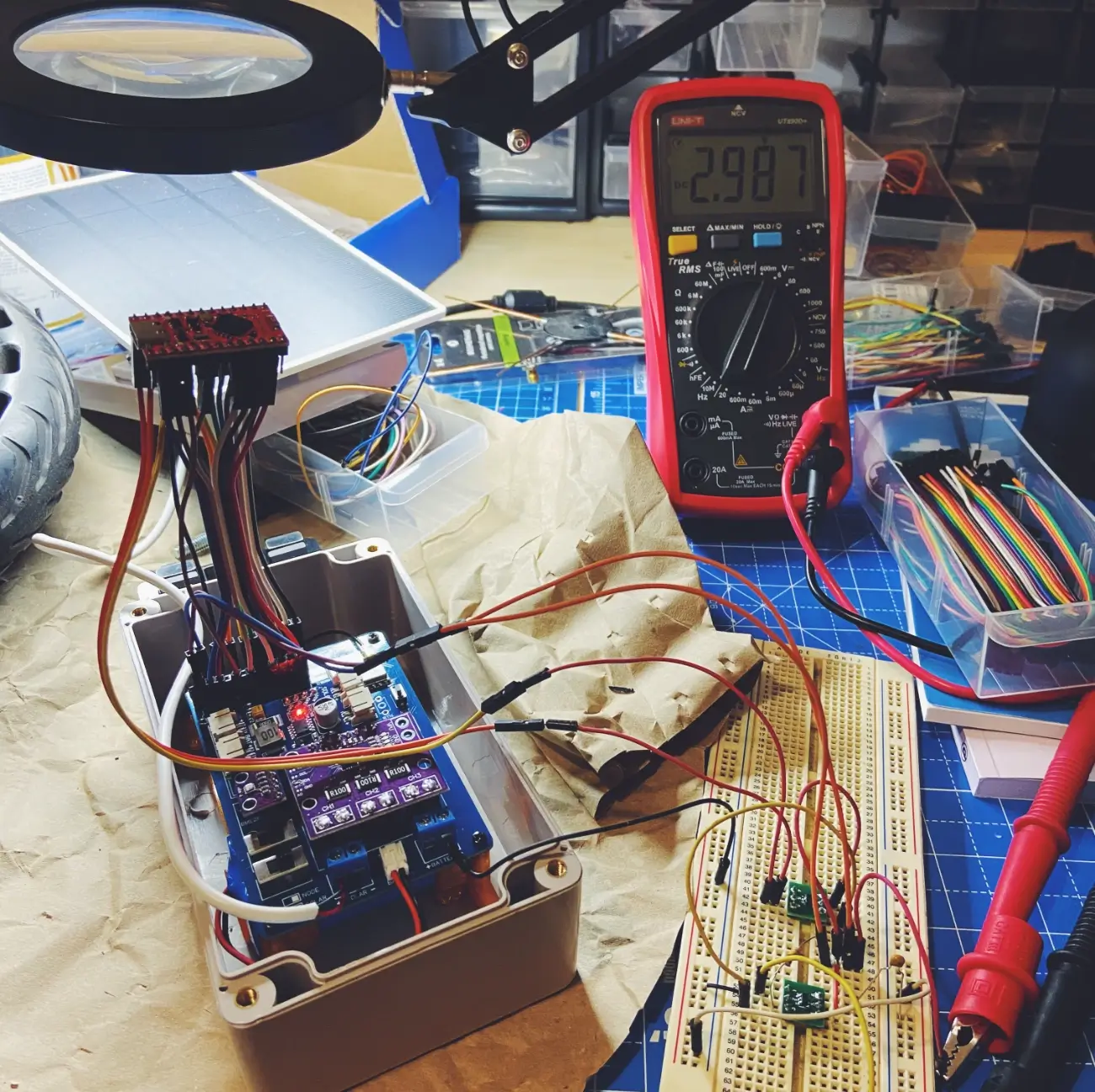
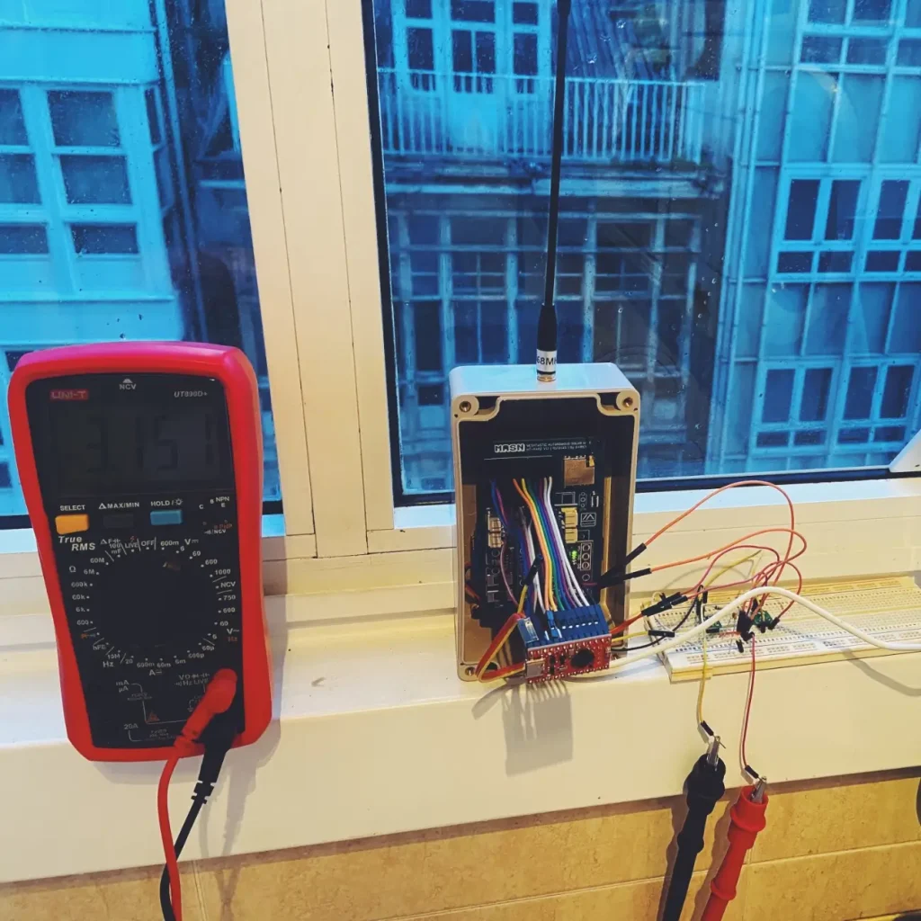
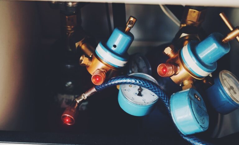
Tests performed
To validate MASN V2.0, tests were carried out focusing on the node’s power behavior. The main goal was to verify that the board responded correctly to low-voltage situations, battery cutoffs, and progressive recovery from the solar panel.
The tests were performed with a laboratory power supply, simulating different input voltage levels and observing the system startup under controlled conditions.
Tested scenarios
| Test | Objective |
|---|---|
| Normal battery power | Check the general operation of the node |
| Full discharge and BMS cutoff | Verify system shutdown |
| Recovery with progressive voltage | Check the behavior during startup |
| Voltage supervisor activation | Validate that the node does not start until it has an adequate voltage |
| Battery reading | Confirm that Meshtastic receives the expected value |
| Operation with solar panel | Review system behavior under real charging conditions |
Photos of the prototype and some tests

Assembly, firmware, and configuration
The general assembly and configuration process for MASN V2.0 is the same as for MASN V1. Firmware installation, the initial Meshtastic setup, enclosure preparation, and basic telemetry settings can be followed from the original article.
For this version, the recommended order of work is as follows:
- Solder the SMD components on the PCB first
- Check continuity and possible solder bridges
- Check the NiceNano / NRF52840 bootloader
- Install the Meshtastic firmware before the final assembly
- Solder the main modules and connectors
- Connect the antenna before powering the node
- Power it initially from the battery and check startup
- Configure the region, node name, and telemetry from the Meshtastic app
- Configure the voltage divider factor in the Meshtastic app
- Verify the battery reading in the application
When downloading and installing the Meshtastic firmware, select the NRF52 Pro-micro DIY device, as in the previous version. After installing the firmware, it is advisable to enable the corresponding telemetry so the node data can be displayed from the application.
Before closing the enclosure, if you are using one, it is recommended to perform a full test with the battery, solar panel, and antenna connected. It is also advisable to check that the battery reading appears correctly in Meshtastic and that the node remains accessible by Bluetooth or through remote administration.
Which board should you build, V1 or V2?
The choice mainly depends on two factors: the assembly difficulty you are comfortable with and the LoRa module you have available.
| Case | Recommended option |
|---|---|
| First MASN build | MASN V1 |
| User with no experience soldering SMD | MASN V1 |
| Node for testing or learning | MASN V1 |
| User with experience soldering SMD | MASN V2.0 |
| Long-term outdoor node | MASN V2.0 |
| Node installed in a hard-to-access location | MASN V2.0 |
MASN V1 remains the easiest option to start with. Its assembly is more direct and requires less soldering precision.
MASN V2.0 is better suited when you need a board prepared for more demanding installations, especially if the node will rely only on battery and solar panel for long periods.
The variant should be chosen based on the LoRa module you plan to use. It is not advisable to order the PCB before this point is clear.
Safety and important warnings
Before powering the node, carefully inspect the assembly. An incorrect solder joint, reversed polarity, or a disconnected antenna can damage components.
Antenna
⚠️ Never power on the node without the antenna connected. You can damage the LoRa module.
Power supply
⚠️ Do not power the node through USB and solar/battery at the same time. You may damage the computer’s USB port.
Polarity
⚠️ Always check polarity before connecting the battery or solar panel. Check it with a multimeter before the first power-up.
SMD components
⚠️ After soldering the SMD components, check that there are no bridges between pads. A visual inspection with a magnifying glass and a basic continuity test can prevent faults that are difficult to locate later.
Battery
⚠️ Use LiPo or lithium-ion batteries with an integrated BMS. Do not use damaged, swollen, or unprotected batteries. The enclosure must allow safe installation, avoiding mechanical pressure on the battery and direct exposure to excessive temperatures.
Radio regulations
⚠️ Configure Meshtastic according to the region where the node will operate. In Europe, the EU868 band should be used, and the applicable power limits must be respected. It is also important to consider antenna gain, as it affects the effective radiated power.
Acknowledgements
The development of MASN V2.0 has been possible thanks to the collaboration and help of several people and communities.
Special thanks to Andrés from Bricolabs for lending me a laboratory power supply to carry out the prototype power tests. This tool made it possible to simulate different voltage scenarios, check the node’s behavior during unstable startups, and validate the changes introduced in this version.
I would also like to thank Bricolabs as a community for the support, technical discussions, and collaborative environment that make it possible for projects like this to be tested, improved, and shared.
Thanks also to TC Robotics for the masterclass on LoRa and for helping me better understand how the protocol works. That knowledge has been very useful for making better decisions during the development of the project.
Finally, an additional acknowledgement to PCBWay, which collaborates with MASN by providing PCBs for the prototyping iterations. This has made it possible to manufacture and test new board revisions more quickly during the development of MASN V2.0.
License: CERN OHL-S v2
MASN is a free and open hardware project, licensed under the CERN Open Hardware Licence Version 2 – Strongly Reciprocal (CERN OHL-S v2).
This means that you can use, manufacture, modify, and share this design freely, even for commercial purposes, as long as you keep the same license and publish any modifications you make.
The goal is to ensure that knowledge and improvements remain accessible to the whole community, fostering an open, collaborative, and transparent ecosystem.
Disclaimer
This project is shared as is, with no guarantee that it will work in every possible scenario.
Each person is responsible for assembling, installing, and using their own node. Before deploying it outdoors, it is advisable to carefully check the solder joints, connection polarity, battery condition, enclosure sealing, and proper antenna mounting.
The use of radio equipment must comply with the regulations applicable in each country or region. Frequency, transmission power, and antenna gain must be configured according to the corresponding legal limits.
It is also the user’s responsibility to verify that the installation is safe from an electrical and mechanical point of view, especially if the node is installed on rooftops, masts, locations exposed to sunlight, or hard-to-access areas.
I feel it lack of below zero charge lockout, is quite important in remote locations.
Hi Silvio.
That is a valid point. The current PCB and the CN3791 charging module do not include a below-zero charging lockout. The protection added in this revision is focused on battery undervoltage and preventing brownout-related startup issues.
For installations exposed to freezing temperatures, the current version should be used with a battery or BMS that has a documented low-temperature charging cutoff. Alternatively, an external low-temperature cutoff can be placed in series with the solar input. For example, an NTC-based temperature controller driving a MOSFET could disconnect the solar panel from the charger when the battery temperature falls below 0 °C, while still allowing the battery to power the node.
The temperature sensor should be attached directly to the battery, ideally with some hysteresis so charging resumes only after the battery has warmed above a safe temperature. This is something I may consider integrating into a future PCB revision.